AP ANKLE PROJECTION
Anteroposterior • Frontal View • Tibioperoneotalar Joint Evaluation
Exposure Factors
Equipment: Without bucky. Position: Supine decubitus or seated.
Plate Size
CENTERING POINT
Precise centering for optimal joint visualization
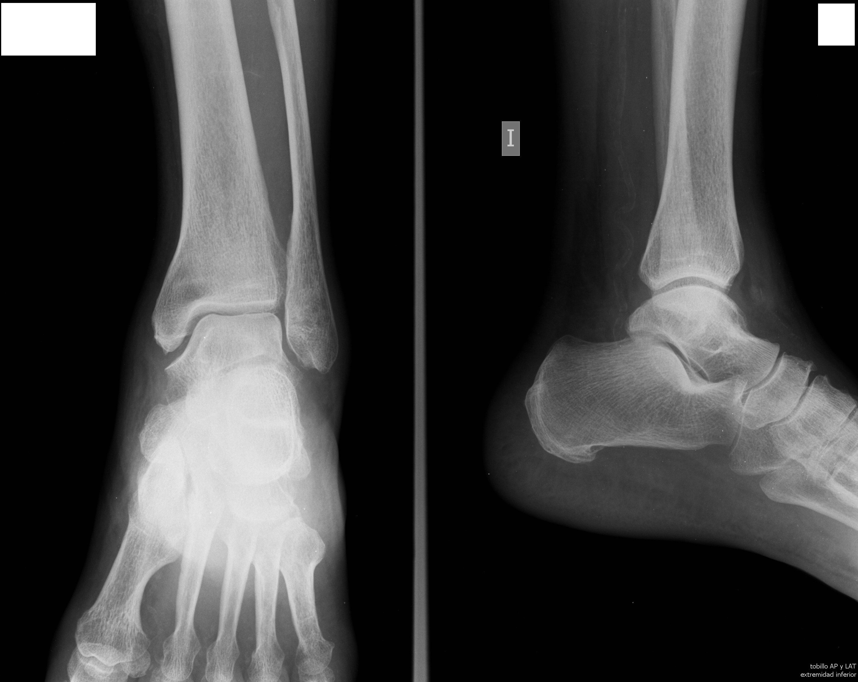
Visible Anatomical Structures
Distal Tibia
Inferior portion
Distal Fibula
Inferior portion
Malleoli
External and internal
Talus
Tarsal bone
- Calcaneus - Heel bone (partially visible)
- Tibiotalar joint - Main ankle joint
- Joint space - Tibioperoneotalar mortise
- Articular surfaces - Of talus and malleoli
- Distal epiphyses - Of tibia and fibula
- Growth line - Metaphysis in young patients
- Articular cartilage - Symmetrical joint space
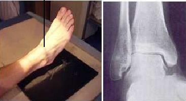
CRITICAL DORSAL FLEXION
The affected foot must be dorsiflexed until the plantar surface is perpendicular to the cassette plane.
This position eliminates structure overlap and allows optimal joint space visualization.
Patient Positioning
Central Ray Direction
Vertical and directed to midpoint between both malleoli
Anatomical point: Midpoint between internal and external malleolus
Entry point: Anterior, at intermalleolar line level
Exit point: Posterior, joint space
Objective: Symmetrical visualization of joint mortise
Patient Instructions
"Remain still during the examination"
Maintain foot dorsiflexion - Do not move ankle during exposure
Technical Considerations
Dorsal Flexion
Dorsiflexion until plantar surface perpendicular to cassette to avoid overlap.
Internal Rotation
Internal rotation of foot to align third toe perpendicular to plate.
Stability
Contralateral flexed position for maximum patient stability.
Clinical Indications
Image Quality Criteria
Joint Space
Tibioperoneotalar joint space symmetrical and visible
Overlap
No significant bone structure overlap
Bone Inclusion
Distal tibia and fibula included, with part of talus
Complete Radiological Study
BASIC ANKLE SERIES
The AP ankle projection is typically complemented with:
These three projections constitute the basic study for ankle trauma evaluation
Resource Optimization
Transversely divided cassette
The 24 × 30 cm cassette is divided transversely in half to:
- Optimize resources - Allows performing two studies with a single cassette
- Reduce costs - Efficiency in radiographic material use
- Maintain quality - Adequate size for ankle anatomical region
Common practice in radiology for distal extremity studies